Due to the increasing population, there is a growing number of vehicles, which has led to a higher demand for parking lots in busy cities. Managing the data of vehicles entering and exiting parking lots can be quite a hassle. So today, I’ve come up with an interesting and inexpensive solution to this problem.
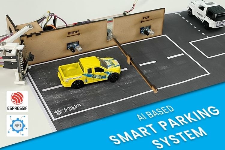
We are going to create a smart parking system with an Automatic Number Plate Recognition (ANPR) system using the affordable ESP32-CAM. With its built-in camera, it is possible to capture images and perform number plate recognition. Additionally, we will manage barrier opening and closing, as well as vehicle entry and exit detection, using IR sensors and more. Without any further delay, let's dive into the project.
Overview of Smart Parking System
This project features a fully automated number plate detection system with barrier control. There are two IR sensors: one at the entry and one at the exit. When a car approaches the entry sensor, the camera on the ESP32-CAM captures the car's number plate and sends it to our dedicated Number Plate Detection API, receiving a response within seconds. The result is gets logged, and the barrier opens to allow the vehicle inside. Similarly, when a vehicle approaches the exit, the barrier opens, allowing the vehicle to leave, and the data gets logged. This is what we’ve planned for this project. It serves as an introductory example of our latest API, which has many more possibilities that I leave to you to explore.
Components Required to Build Smart Parking System
The most important component here is the ESP32-CAM, which was chosen for being an affordable microcontroller development board with essential features like a camera and Wi-Fi. If any other microcontrollers fit these criteria, you can select them as well. The rest of the components are based on our own concept. As always, you're not limited to the list provided below; feel free to customize it as needed.
Below is the list of components that are required,
- ESP32 CAM x1
- Servo Motor x1
- IR Sensor Module x2
- Any USB to UART Converter x1
- Breadboard x1
- Jumper Wires (Required Quantity)
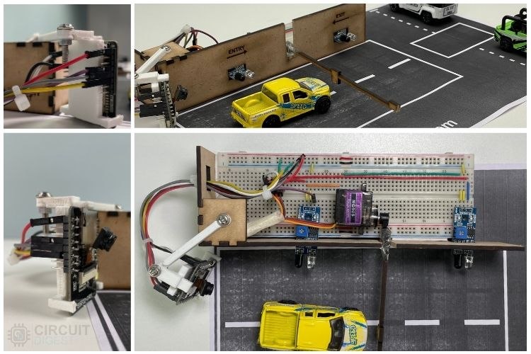
To mount the ESP32-CAM and add aesthetics to the project, I’ve used 3D printing and 2D laser cutting. However, these are not necessary in your case, as there are many alternatives to fulfill these tasks.
Circuit Diagram for the Smart Parking Management System
Finally, we come to the actual hardware connection. The circuit diagram is quite simple and self-explanatory. The main connections will be between the ESP32-CAM, servo motor, and IR sensors, with the rest dedicated to the power supply circuit. One important thing to remember is that the servo motor is powered by 5V, and the IR sensors are powered by the 3.3V output from the ESP32-CAM. This ensures that the digital output from the IR sensors won't exceed the 3.3V limit of the ESP32-CAM's GPIOs. I'm going to provide a 5V power supply using an old USB wire I found lying around, but you can use any 5V source available.
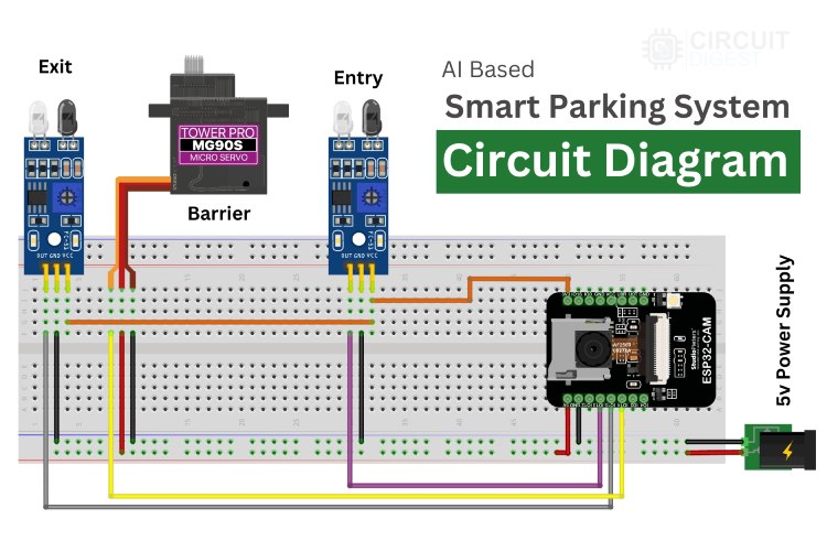
Above, you can see the circuit diagram of the smart parking system we are going to build. Let me explain the circuit connections in detail for clarity.
We are utilizing three GPIOs of the ESP32-CAM, one for the servomotor and two for the IR sensors. GPIO 14, configured as PWM output, controls the shaft position of the servo motor. GPIO 15 and GPIO 13, configured as digital inputs, are connected to the two IR sensors, representing the entry and exit points.
Regarding the power supply, we need an input voltage of 5V for the overall circuit. Inside the circuit, we need 3.3V for the IR sensors and the ESP32 module within the ESP32-CAM module, which can be drawn from the built-in voltage regulator of the ESP32-CAM module.
That's it—connection complete!
I'm not going to repeat the programming process for the ESP32-CAM development module, as we already have a dedicated article explaining the concept. For beginners, I recommend checking out the article - How to Programme the ESP32-CAM? to see the circuit diagram between the USB-to-UART converter module and ESP32-CAM and to learn about the programming modes of the ESP32-CAM and more.
ESP32-CAM Code for Smart Parking System
Now comes the final part of the project- coding. However, before diving into the code, there are prerequisites such as generating the API Key and installing additional libraries.
Generating API KEY
You need to generate an API Key for accessing the number plate recognition API. Please refer to the section on "Generating API Key" to learn more about this process.
Once you've obtained the API Key, we can proceed with the coding phase, starting with installing the required libraries.
Installing Additional Libraries
We need to install two libraries to proceed with the code,
You can install these libraries directly via the provided GitHub link or by searching for them in the Arduino IDE library manager.
ESP32 Code Explnation
To learn more about the Number Plate Recognition API, its working demonstration, and the detailed code explanation, you are welcome to explore another article dedicated to this topic License Plate Recognition using ESP32-CAM. This is because I will be skipping the most repetitive parts of the code in this explanation.
Including Required Libraries
Initially, the necessary libraries are included in the code. Don't worry about the number of libraries listed in the image—most of them are built-in and will be automatically located when you select the AI Tinker ESP32-CAM Board in the board manager.
// Libraries for WiFi, Secure Client, and Camera functionalities
#include <Arduino.h>
#include <WiFi.h>
#include <WiFiClientSecure.h>
#include <WebServer.h>
#include "soc/soc.h"
#include "soc/rtc_cntl_reg.h"
#include "esp_camera.h"
#include <NTPClient.h>
#include <WiFiUdp.h>
#include <ESP32Servo.h>

// WiFi credentials and server information
const char* ssid = "xxx";             // Replace xxx with your WiFi SSID
const char* password = "xxx";          // Replace xxx with your WiFi Password
String serverName = "www.circuitdigest.cloud";  // Replace with your server domain
String serverPath = "/readnumberplate";         // API endpoint path "/readqrcode" or "/readnumberplate"
const int serverPort = 443;                     // HTTPS port
String apiKey = "xxx";                 // Replace xxx with your API key
String imageViewLink = "https://www.circuitdigest.cloud/static/" + apiKey + ".jpeg";
#define flashLight 4  // GPIO pin for the flashlight
int count = 0;        // Counter for image uploads
Next, you will notice some placeholder text like “xxx.” These are areas where you need to replace them with your own details, such as your API key. Other than these changes, if you are replicating this project as is, there are no other modifications required. However, if you plan to adapt the project to your own needs, some adjustments may be necessary.
Pin Declarations and Functions
After initializing the required libraries, the next step is pin declaration. This involves assigning GPIO pins to the peripheral devices, such as the two IR sensors and the servo motor. Below, you can see the image showing the GPIO pin numbers allocated:
- GPIO 14 for the Servo Motor
- GPIO 13 for the Entry IR Sensor
- GPIO 15 for the Exit IR Sensor
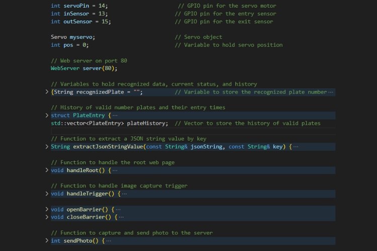
Now, let's take a closer look at the key functions defined in the code for this smart parking system:
- PlateEntry(): The PlateEntry structure represents the vehicle's valid number plate information and its entry time. When a vehicle's number plate is recognized, this structure stores the plate number and entry time for record-keeping and display on the web interface.
- extractJsonStringValue(): This function extracts a value from a JSON string based on a given key. It’s used to retrieve specific data, such as the recognized license plate number or an image link, from the server’s JSON response after sending a photo.
- handleRoot(): The handleRoot function generates and serves the HTML content for the root web page of the smart parking system. It provides the main interface for the system, which is accessed through a web browser.
- handleTrigger(): This function handles the action of triggering an image capture, initiated either by the web interface or another trigger, such as when a vehicle is detected entering the parking area.
- openBarrier(): The openBarrier function controls the servo motor to open the parking barrier, allowing entry after a vehicle has been successfully recognized and verified.
- closeBarrier(): This function controls the servo motor to close the parking barrier after the vehicle has entered the parking area, securing the parking lot.
- sendPhoto(): This critical function captures a photo using the ESP32-CAM and uploads it to the server for license plate recognition. It handles both image capture and server communication, which drive the logic for opening or closing the parking barrier.
These functions work together to manage the core tasks of the smart parking system, including handling the web interface, capturing and uploading photos for recognition, and controlling the parking barrier based on recognition results.
Main Functions
In this project, the most significant functions are the setup() and loop() functions, which are fundamental to the operation of the smart parking system. Let’s explore them in detail.
void loop() {
  // Update the NTP client to get the current time
  timeClient.update();
  currentTime = timeClient.getFormattedTime();

  // Check the web server for any incoming client requests
  server.handleClient();

  // Monitor sensor states for vehicle entry/exit
  if (digitalRead(inSensor) == LOW && vehicalCount < availableSpaces) {
    delay(2000);      // delay for vehicle need to be in a position
    handleTrigger();  // Trigger image capture for entry
  }

  if (digitalRead(outSensor) == LOW && vehicalCount > 0) {
    delay(2000);  // delay for vehicle need to be in a position

    openBarrier();
    PlateEntry newExit;
    newExit.plateNumber = "NULL-Exit";
    newExit.time = currentTime;  // Use the current timestamp
    plateHistory.push_back(newExit);
    delay(barrierDelay);
    vehicalCount--;
    closeBarrier();

    currentStatus = "Idle";
    server.handleClient();  // Update status on webpage
  }
}
Setup() Function
The setup() function runs once at the start and is responsible for initializing hardware components and establishing network connectivity. Below are the key tasks it performs:
- Brownout Detector Disable, This prevents the ESP32 from resetting due to voltage fluctuations during power-up.
- Serial Communication & Pin Setup, Initializes serial communication for debugging and configures GPIO pins for the servo motor and IR sensors.
- Wi-Fi Setup, Establishes a Wi-Fi connection, which is critical for connecting to the number plate recognition API and serving the web interface.
- NTPClient Initialization, Sets up the NTP client for fetching the current time. This will be used for timestamping vehicle entries and exits.
- Web Server Setup, Initializes the web server to handle client requests, such as displaying vehicle data or triggering image capture.
- Camera Configuration, Configures the ESP32-CAM module, ensuring it’s ready to capture images for license plate recognition.
- PWM and Servo Initialization, Initializes the PWM (Pulse Width Modulation) signal for controlling the servo motor, which will open and close the barrier.
Loop() Function
The loop() function runs continuously and manages the main functionality of the system. Here’s a breakdown of what it does:
NTP Time Update
The NTP client is updated periodically to fetch the current time. This time is used for timestamping when vehicles enter and exit the parking lot.
Web Server Handling
Continuously checks for incoming web client requests and handles them, such as serving the web interface or responding to commands.
Vehicle Entry Handling
- When the inSensor detects a vehicle and there is available space in the parking lot, the system delays briefly to ensure the vehicle is properly positioned.
- It then calls the handleTrigger() function to capture an image of the vehicle’s license plate for recognition.
- If the recognition is successful, the system logs the vehicle entry and opens the barrier to allow the vehicle inside.
Vehicle Exit Handling
- When the outSensor detects a vehicle, and the vehicle count is greater than zero, the system opens the barrier and logs the exit time (marked as "NULL-Exit" for simplicity).
- After a delay (giving the vehicle time to pass through), the barrier is closed, and the vehicle count is decremented.
These functions work together to manage the core operations of the smart parking system, including vehicle detection, image capture, number plate recognition, barrier control, and record-keeping. Please note that this code is not yet fully optimized for direct implementation. It requires additional work to enhance error handling and overall robustness. This aspect of the project is left to be refined and perfected.
Now, let’s upload the code and check the result.
Working Demonstration of Smart Parking System
Finally, after successfully uploading the code, you can see the expected result in the GIF video below. The overall system delay is set long because it is a prototype. For deployment, it can be optimized to provide faster results. The only thing causing delay is uploading and waiting for the result, which is unavoidable with this approach to number plate recognition.
To simplify, we are recognizing the number plate only at the entry, but this can be improved to recognize both entry and exit. In this project, we are storing vehicle data only in RAM, which might not be available after a restart. In that case, you can use any online IoT platform to store the data in the cloud or use the built-in memory card slot to log the data, so it will be available even after a power down.
Successfully, we have created a Smart Parking System with these advanced features. Keep tuning and optimizing this project, and we will meet again with another exciting project soon.